Smartone-C Installation - Wiki
Installing Batteries
The SmartOne C is powered by, and comes with, four installed 1.5v Lithium AAA batteries. The battery compartment is accessible from the bottom of the device by removing the four Philips head screws.
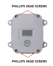
Remove the water-tight cover and insert the batteries to align with the positive and negative marker. When the batteries are removed and replaced the device will retain its configuration.
CAUTION: Upon replacing the Battery Compartment Cover, tighten the screws according to specification (36 inch-ounces); otherwise the unit may no longer retain its water-tight capability. Ensure the cover is reinstalled and tightened to specification (36 inch-ounces)
Battery Life Estimate
Battery life is dependent on several factors:
- View of the sky
- How often the device is transmitting
- Requesting GPS fixes
- Temperature
- Sleep Current
The below table is an example of clear sky transmissions :
| Messages per Day | Estimated battery Life (Days) |
|---|---|
| 1 | 750 days |
| 2 | 500 days |
| 3 | 400 days |
| 6 | 200 days |
| 24 | 80 days |
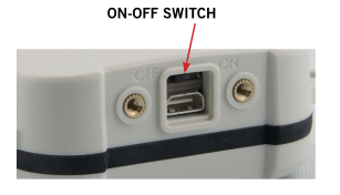
Turning On and Off
To turn the device ON or OFF, remove the connector cover from the end of the device. Then slide the switch actuator towards the desired direction of the ON or OFF markings.
Mounting
The SmartOne is designed to be mounted to an asset using double-sided adhesive tape and/or the included mounting bracket. The mounting bracket includes 4 threaded pem nuts and 4 screws which allow easy attachment to the SmartOne. The bracket also has four additional through-holes, used for mounting to assets (screws for asset mounting not included).
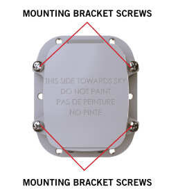
The included mounting options allow for various secure mounting methods while providing proper orientation of the device for reliable communication with Globalstar's satellite constellation.
NOTE: The antenna is located under the product’s cover where the statement “THIS SIDE TOWARDS SKY DO NOT PAINT” is seen.
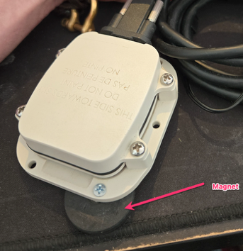
Here's some more ideas of mounting :
Collar for cattle

Magnet for temporary and quick install
Wiring
| Color | Function |
|---|---|
| Brown | Setup (Handshake from Serial Device) |
| Red | RX |
| Orange | TX (to Serial Device RX) |
| Light Blue | Dry Contact 2 |
| White | Dry Contact 1 |
| Yellow | Soft Power Down (Normally Open) |
| Green | Ground |
| Blue | Ground |
| Violet | Line Power + |
- When using the 5V external input cable, the supply voltage applied to theLine Power + wire must be 5.0 VDC +/- 0.25 VDC. Applying a different voltage will either damage the SmartOneC or cause it to function improperly/shutdown.
- When using the 8-22 V external input cable, the supply voltage applied to the Line Power + wire must be between 8.0 VDC and 22VDC. If less than 8 VDC is applied, the regulator will not function properly. If more than 22VDC is applied, there is a chance that the regulator will be damaged.
- This cable is designed to work with 3.3 V logic only. Do not use with 5 V logic devices.
- Be certain that unused wires do not short to each other.
- All ground wires are common; therefore, any ground can be used with any function.
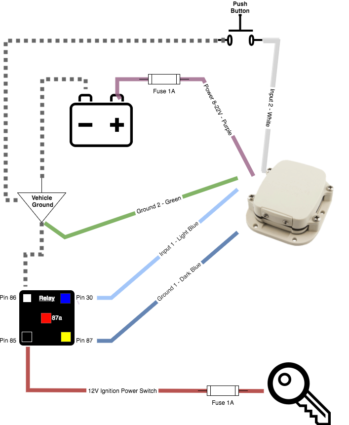
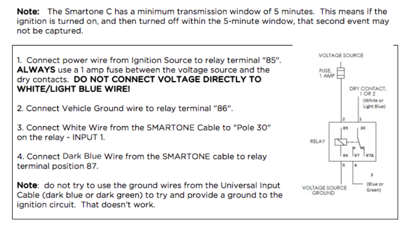
Here's an example of a vehicle wiring scheme to get the engine ignition status using a relay
There are no comments for now.
to be the first to leave a comment.